development log, part two
in which the chassis is converted to tiltable.
last updated 6/27/1999
Your comments are always welcome. Send me email!
The story resumes now, after a total cost of $240 and total time of 21 hours, with a work-in-progress three-wheeled rolling chassis. (The story started with Part One, of course.)
The arguments that got me to this design were these:And so it resumes. Happily, happily.Since December, thinking and planning adds these considerations:
- one wheel in front means no steering linkage is necessary; it can be borrowed from a motorcycle
- two rear wheels is no less stable than a two-front-wheel config IF (!) cg is low
- typically, a driven pair of wheels, rear wheels in this case, needs a differential. But let's try without... motorcycles w/sidecars do it all the time. (ignore the fact they are notoriously hard to drive.)
Which led me to these conclusions:
- modeling the stability (in a pretty cool spreadsheet analysis) leads me to believe my simple trike's 30.5" track width would be capable of an 0.6g turn; and that's a little light. (A three- or four-wheeled vehicle should always skid long before it rolls over!)
- the 3hp electric motor (roughly equivalent to a 9hp gas motor) is sufficient for flat ground, but is wanting for hills and headwinds
And my answers to these problems are:
- I need to widen the track width to something between 40" and 48" to get me up closer to a 1g stability limit
- I need more power (Now, Scotty! [grin])
But HO! Opportunity knocks: since I am cutting the rear wheel modules away, why not make them tiltable? Fine, but the lessons I learned from building the first Commutamatic must be considered:
- I'll cut away the back wheels' frames and suspensions to widen their spacing
- I'll still have no differential or transmission but still add a second motor; each rear wheel gets its own
So here are the design rules for the Maxion now:
- steering levers (instead of handlebars) the way I had them were unnatural. (I had in mind the safety consideration that no steering column should be aimed at the driver's sternum.)
- foot pedals for controlling lean can get you into a weird kind of brain-lock (in which your leg fights your arm) that natural or active (automated) lean is the way to go
- the driver's seat was too high (one of the reasons was that the rear end/drive module I built forced the driver to be high, another was the clearance for tilting OVER that same module instead of in front)
- leaning may just be too much complexity, and I almost welded it into non-tilting solidity for good in the Commutamatic
The result is going to be something like a decades-old bike with sidecar design I read about, in which the sidecar was attached by a parallelogram linkage. More recently, Antonio Baptista Carlos Sanjuan built a proof-of- concept bike in 1998 that seems to be this way (see it on the TTW Motorized Prototypes page at the site).
- handlebar steering, either ahead of the driver or on a pivot under the driver's mid-thigh, to remove the aforementioned unnatural feel of the levers I concocted
- natural lean with the option of converting to active (feet are free for accelerator and brake (right foot) and tilt-lock (left foot, instead of a clutch))
- make track width wide enough that if I have to NOT lean for safety reasons, the trike will be stable as an unarticulated chassis
- make all three wheels tilt, since the motorcycle chassis whence came my "modules" were not designed for lateral forces, just vertical
Through Feb 16, 1999. Incidental events, plus getting back to work cutting and preparing.Total cost so far: $380. Total time so far: 28 hours.
- Buy another golf cart ($50) from my pusher (I got the golf cart monkey on my back, man) Jack Barnes. (Thanks, Jack.) (Among the recyclable components on it: adjustable steering linkage parts, foot pedals, switches, high current reverse switch, 3hp DC motor, a "fuel gauge")
- Get registration and new title. How nice! ($50) I have the license plate ready... that counts.
- Separate (euphemism for "attack with a reciprocating saw") my precious rolling chassis into three parts: left rear module, right rear module, front module.
- Buy 3/4" round, solid steel rod, 3/4" i.d., 1" o.d. brass bushings for tilting joints ($20)
- Buy more 3/4" round, solid steel rod, and small rod stock for tension elements in frame, ($20)
- Weld up the bottom tilt link points to the two rear wheel modules. (Will need strengthening later.)
Sketches of effect of "rear wheel push" design. The trigonometry of a possible design. As The Fresh Prince once said, or maybe didn't, "Get Triggy With It!" (Big up to my students who groan over my jokes.)One of the possibilities was an active tilting mechanism that would "push" the outside rear wheel down relative to the frame. The effect would be to lift the rear corner, while widening, a little, the track width, and shifting, a little, the cg toward the inside of the turn.
The result? A 12" lowering of a rear wheel (a 12" lift of a rear corner, therefore) would tilt the frame about 22 degrees, pitch it forward about 5 degrees, would widen the track by about 3", raise the cg by about 6", though it would also shift it toward the center of the turn by about 7". The combination of the shifting and lifting would have given the equivalent stabilty of a 48" track width; impressive compared to the 30.5" width untipped. It brings the theoretical topple acceleration from 0.6g up to about 1.0g.
There are reasons why I chose not to do this, not least of which is the difficulty in delivering torque to the rear wheel while pushing it around. Not to mention, "Automatic" tilt control (lateral acceleration is sensed, and actuators force the chassis into leaning) still hasn't won me over.
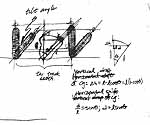
Sketches of effect of three-wheel tilt design. The trigonometry of the current design. By tipping the wheels, the cg is shifted lower and toward the inside of the turn.Total cost so far: $380. Total time so far: 30 hours.The ultimate choice is to have all three wheels tilt. The angle of tilt for all three wheels is identical; parallelogram linkages maintain this consistency.
The result? At the planned maximum tilt of 45 degrees, the cg is lowered fully 6", shifted to to the inside by over 12", and creates an effective track width of about 66". Together, these changes bring the theoretical topple acceleration from 0.8g (for the untilted 40" track width) up to about 1.9g. Now we're talkin'.
Through Mar 19, 1999. Incidental stuff, and a little cutting and welding.Total cost so far: $436. Total time so far: 34 hours.
- Order 12 sway bar bushings and mounts. (These will support brass bushings which are the pivot points for lean. Thanks JC Whitney.) $60.
- Order windshield washer tank, pump and nozzle. $16. (Now there's wishful purchasing, eh?)
- Weld up the top tilt link points to the two rear wheel modules.
- Prop stuff up with plywood and 2x4s for measurement and visualization.
Through Mar 21, 1999. Some real progress on the chassis. Today included a LOT of standing and staring and imagining. (It's frustrating, but you can't proceed until you know where you are going. And even when you think you know where you're going, you sometimes get lost.)Total cost so far: $481. Total time so far: 41 hours.
- Buy more steel. $25.
- Use temporary straps to create tilting pivot points on 2x4 (wood) cross-members.
- Weld on "keel" to the cabin, with its two tilting points along the bottom.
- With plywood and clamps, place seat in cabin (such as it is) and verify ergonomic fit.
- With plywood and clamps, swing +/- 45 degrees to look for clearance problems. OK!
- Weld up vertical member to roll cage, weld on pivot rod.
- Cut away some of the OLD parts (from the pre-tilting phase).
- Weld on a few braces.